Visit us at
www.anaren.com
USA/Canada:
Toll Free:
Europe:
Asia:
(315) 432-8909
(800) 411-6596
+44 2392-232392
+86 512-62749282
odel
05 0
HF
Rev B
Ultra Low Profile 1608 Balun
50 to 50 Balanced
Description
The BD0205F5050AHF is a low profile sub-miniature balanced to unbalanced
transformer designed for differential input locations on data conversion devices such
as A to D and D to A converters. In an easy to use surface mount package covering
75 MHz to 1000 MHz and with CMRR performances over 2x that of the incumbent
wire wound products, this transformer is optimized to offer improved SFDR
management during operation of the data converter device. The BD0205F5050AHF
is ideal for high volume manufacturing and is higher performance and smaller form
factor than traditional wire wound transformers. The BD0205F5050AHF has an
unbalanced port impedance of 50 and a 50 balanced port impedance. This
transformation enables single ended signals to be applied to differential ports on the
data converter devices. The output ports have equal amplitude (-3dB) with 180
degree phase differential. The BD0205F5050AHF is available on tape and reel for
pick and place high volume manufacturing.
Detailed Electrical Specifications:
Specifications subject to change without notice.
ROOM (25?/SPAN>
??/DIV>
?SPAN class="pst BD0205F5050AHF_2591984_11">C)
Parameter
Min.
Typ.
Max
Min.
Typ.
Max
Unit
Frequency
70
1000
200
500
MHz
Unbalanced Port Impedance
50
50
Ohm
Balanced Port Impedance
50
50
Ohm
Return Loss
4
4.6
11
13
dB
Insertion Loss*
3.0
3.4
0.9
1.1
dB
Amplitude Balance
0.2
0.6
0.2
0.6
dB
Phase Balance
1
3
1
3
Degrees
CMRR
36
36
dB
Power Handling
2
2
Watts
Features:
" 70 1000 MHz (IL 3dB BW)
" 200-500 MHz ( IL 1dB BW)
" 0.83 mm Height Profile
" 50 Ohm to 2 x 25 Ohm
" Excellent CMRR (36dB typical)
" Input to Output DC Isolation
" Surface Mountable
" Tape & Reel
" Non-conductive Top Surface
" RoHS Compliant
" Halogen Free
Operating Temperature
-55
+85
-55
+85
篊
* Insertion Loss stated at room temperature (Insertion Loss is approximately 0.1 dB higher at +85 篊)
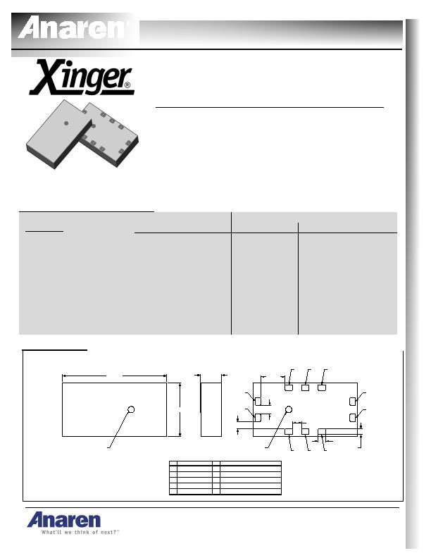
Outline Drawing
4x .96
4x .35
4x .28
10x .30
10x .22
2x .35
Orientation
Marker
Orientation
Marker
1
2
3
4
5
8
7
6
10
2
1 Unbalanced
OPEN
Pin Designation
3
4
5
GND
GND
GND
7
6
Balanced port 1
Open
Pin Designation
8
9
10
GND
GND
Balanced port 2
.84?/SPAN>.08
4.10?/SPAN>.10
2.10?/SPAN>.10
9
Top View (Near-side)
Side View
Bottom View (Far-side)
Mechanical Outline
Dimensions are in Millimeters
发布紧急采购,3分钟左右您将得到回复。
相关PDF资料
BD0810J50100AHF
XFRMR BALUN RF 800-1000MHZ 0805
BD0810J50200AHF
XFRMR BALUN RF 800-2000MHZ 0805
BD0826J50200AHF
XFRMR BALUN RF 800-2600MHZ 0805
BD1631J50100AHF
XFRMR BALUN RF 1.6-3.1GHZ 0805
BD1722N5050AHF
XFRMR BALUN RF 1700-2200MHZ 0404
BD2425N100ATI
XFRMR BALUN RF 2400-2500MHZ 0404
BD2425N50100AHF
XFRMR BALUN RF 2400-2500MHZ 0404
BD2425N50200AHF
XFRMR BALUN RF 2400-2500MHZ 0404
相关代理商/技术参数
BD021-04A-A1-0350-0200-0550-LD
制造商:Global Connector Technology (GCT) 功能描述:BOARD-BOARD CONNECTOR HEADER 4WAY 1ROW 制造商:Global Connector Technology (GCT) 功能描述:BOARD-BOARD CONNECTOR HEADER, 4WAY, 1ROW 制造商:Global Connector Technology (GCT) 功能描述:BOARD-BOARD CONNECTOR HEADER, 4WAY, 1ROW; Series:-; Pitch Spacing:1.27mm; No. of Rows:1; No. of Contacts:4; Gender:Header; Contact Termination:Surface Mount Vertical; Contact Plating:Gold; Contact Material:Copper Alloy ;RoHS Compliant: Yes
BD021-05A-A1-0350-0200-0550-LD
制造商:Global Connector Technology (GCT) 功能描述:BOARD-BOARD CONNECTOR HEADER 5WAY 1ROW 制造商:Global Connector Technology (GCT) 功能描述:BOARD-BOARD CONNECTOR HEADER, 5WAY, 1ROW 制造商:Global Connector Technology (GCT) 功能描述:BOARD-BOARD CONNECTOR HEADER, 5WAY, 1ROW; Series:-; Pitch Spacing:1.27mm; No. of Rows:1; No. of Contacts:5; Gender:Header; Contact Termination:Surface Mount Vertical; Contact Plating:Gold; Contact Material:Copper Alloy ;RoHS Compliant: Yes
BD021-06A-A1-0350-0200-0550-LD
制造商:Global Connector Technology (GCT) 功能描述:BOARD-BOARD CONNECTOR HEADER 6WAY 1ROW 制造商:Global Connector Technology (GCT) 功能描述:BOARD-BOARD CONNECTOR HEADER, 6WAY, 1ROW 制造商:Global Connector Technology (GCT) 功能描述:BOARD-BOARD CONNECTOR HEADER, 6WAY, 1ROW; Series:-; Pitch Spacing:1.27mm; No. of Rows:1; No. of Contacts:6; Gender:Header; Contact Termination:Surface Mount Vertical; Contact Plating:Gold; Contact Material:Copper Alloy ;RoHS Compliant: Yes
BD021-07A-A1-0350-0200-0550-LD
制造商:Global Connector Technology (GCT) 功能描述:BOARD-BOARD CONNECTOR HEADER 7WAY 1ROW 制造商:Global Connector Technology (GCT) 功能描述:BOARD-BOARD CONNECTOR HEADER, 7WAY, 1ROW 制造商:Global Connector Technology (GCT) 功能描述:BOARD-BOARD CONNECTOR HEADER, 7WAY, 1ROW; Series:-; Pitch Spacing:1.27mm; No. of Rows:1; No. of Contacts:7; Gender:Header; Contact Termination:Surface Mount Vertical; Contact Plating:Gold; Contact Material:Copper Alloy ;RoHS Compliant: Yes
BD021-08A-A1-0350-0200-0550-LD
制造商:Global Connector Technology (GCT) 功能描述:BOARD-BOARD CONNECTOR HEADER 8WAY 1ROW 制造商:Global Connector Technology (GCT) 功能描述:BOARD-BOARD CONNECTOR HEADER, 8WAY, 1ROW; Series:-; Pitch Spacing:1.27mm; No. of Rows:1; No. of Contacts:8; Gender:Header; Contact Termination:Surface Mount Vertical; Contact Plating:Gold; Contact Material:Copper Alloy ;RoHS Compliant: Yes
BD021-09A-A1-0350-0200-0550-LD
制造商:Global Connector Technology (GCT) 功能描述:BOARD-BOARD CONNECTOR HEADER 9WAY 1ROW 制造商:Global Connector Technology (GCT) 功能描述:BOARD-BOARD CONNECTOR HEADER, 9WAY, 1ROW 制造商:Global Connector Technology (GCT) 功能描述:BOARD-BOARD CONNECTOR HEADER, 9WAY, 1ROW; Series:-; Pitch Spacing:1.27mm; No. of Rows:1; No. of Contacts:9; Gender:Header; Contact Termination:Surface Mount Vertical; Contact Plating:Gold; Contact Material:Copper Alloy ;RoHS Compliant: Yes
BD021-10A-A1-0350-0200-0550-LD
制造商:Global Connector Technology (GCT) 功能描述:BOARD-BOARD CONN HEADER 10WAY 1ROW 制造商:Global Connector Technology (GCT) 功能描述:BOARD-BOARD CONN, HEADER, 10WAY, 1ROW 制造商:Global Connector Technology (GCT) 功能描述:BOARD-BOARD CONN, HEADER, 10WAY, 1ROW; Series:-; Pitch Spacing:1.27mm; No. of Rows:1; No. of Contacts:10; Gender:Header; Contact Termination:Surface Mount Vertical; Contact Plating:Gold; Contact Material:Copper Alloy ;RoHS Compliant: Yes
BD-02AFFM-QL8D01
功能描述:STANDARD 制造商:amphenol ltw 系列:* 零件状态:在售 标准包装:10